INTRODUCTION TO LOGIC GATES
Definitions:
- A gate is an electronic device which is used to computer a function on a two valued signal
- logic gates are the basic building block of digital circuits
- A truth table is a method of representing or calculating the result of every combination of inputs in a Boolean expression
- Most logic gates have two inputs and one output
- A logic gate is represented as a logic diagram and also have a corresponding truth table
- At any given moment, every terminal is in one of the two binary conditions low (0) or high (1)
TYPES OF LOGIC GATES WITH SYMBOL AND TRUTH TABLE
- NOT GATE
- A NOT gate accepts one input value and produces one output value
- By definition, if the input value of a NOT gate is low (0), the output value is high (1), and if the input is high (1) the output is low (0)
- A not gate is also referred to as an inverter because it inverts the input value

- AND GATE
- An AND gate accepts two input signals
- The AND gate is an electronic circuit that gives High output (1) only if all the two inputs are High.
- A dot (.) is used for the expression e.g. A.B or just writing the two inputs together without a sign e.g. AB.

- OR GATE
- The OR gate is an electronic circuit that gives a high output (i) if one or more of its input are high.
- A plus (+) sign is used to show the OR operation

Combining the NOT GATE with AND gate and the NOR gate
- NAND GATE
- This gate stands for NOT-AND gate which is equal to an AND gate followed by a NOT gate.
- The output of all NAND gates are High if any of the input are low
- The Symbol is an AND gate with a small circle on the output
- The small circle represents inversion or the NOT gate
- It can be expressed with a bar above it .or (A.B)’ or .

- NOR GATE
- This is a NOT OR gate which is equal to an OR gate followed by a NOT gate.
- The output of all NOR gate are low if any of the Input are high
- The symbol is an OR gate with a small circle on the output
- The small circle represents inversion
- It can be expressed with a bar above it or (A+B)’

- XOR GATE
- This gate stands for Exclusive OR gate
- An XOR gate produces an output low (0) if its two input are the same and provides high (1) if the two inputs are different

- XNOR
- The exclusive NOR gate is logically equivalent to an XOR gate followed by an inverter

COMBINING LOGIC GATES
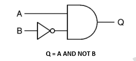
Logic gates can be combined to produce more complex functions
e.g., To produce Q which is true only when Input A is true and input B is false, we can combine a NOT gate and the AND gates shown

Q = A AND NOT B
Working out the function of a combination of gates
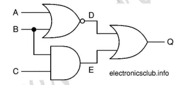
Truth tables can be used to work out the function of a combination of gates such as the system shown below:

Begin by creating a table showing all possible combinations of inputs (A, B and C in this example) with enough extra columns for each intermediate output (D and E in this example) as well as the final output (Q).
Then work out all the intermediate output states, filling in the table as you do go.
These intermediate outputs form the inputs to the next gate (or gates) so you can use these to work out the next output(s), in this example that is for the final output (Q).
D = NOT (A OR B)
E = B AND C
Q = D OR E = (NOT (A OR B)) OR (B AND C)
The truth table shows the intermediate outputs D and E as well as the final output Q.
| Inputs | Outputs | ||||
| A | B | C | D | E | Q |
| 0 | 0 | 0 | 1 | 0 | 1 |
| 0 | 0 | 1 | 1 | 0 | 1 |
| 0 | 1 | 0 | 0 | 0 | 0 |
| 0 | 1 | 1 | 0 | 1 | 1 |
| 1 | 0 | 0 | 0 | 0 | 0 |
| 1 | 0 | 1 | 0 | 0 | 0 |
| 1 | 1 | 0 | 0 | 0 | 0 |
| 1 | 1 | 1 | 0 | 1 | 1 |


