What is a Logic Gate?
A logic gate is an elementary building block of a digital circuit. It is an electronic circuit implementing a Boolean function — a logical operation performed on one or more binary inputs that produces a single binary output. Digital logic systems are based on the binary (two-level) number system (1 or 0, high or low, on or off, true or false).
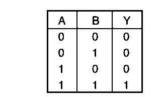
A truth table shows every possible input combination to a gate or circuit, with the resulting output for each combination. To construct a truth table, we evaluate the Boolean expression for all possible combinations of the input variables — the number of combinations is always 2n, where n is the number of input variables.
NOT Gate
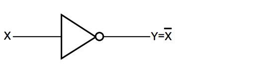
The simplest gate is the “inverter” or NOT gate. It has just one input, and the output is its opposite: if the input is high (1), the output is low (0), and vice versa. NOT operation on X is denoted X̅ or X’, so if X is the input, output Y = X̅.
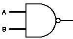
AND Gate
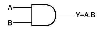
An AND gate has two inputs and a single output, which is 1 only if both inputs are 1 — like a lighting circuit with two switches in series, where the lamp lights only if both switches are pressed. Y = A.B, read as “Y equals A AND B”.
OR Gate
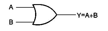
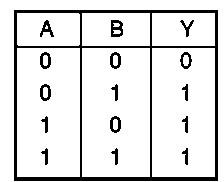
An OR gate gives a high output if any of the inputs is high — like a lighting circuit with two switches in parallel, where the lamp lights if either switch is pressed. The OR gate performs logical addition; Y = A+B, read as “Y equals A OR B”.